Файл:Heat pump system on rainwater pit.png
Heat_pump_system_on_rainwater_pit.png (442 × 436 пкс, размер файла: 6 КБ, MIME-тип: image/png)
Этот файл находится на Викискладе. Сведения о нём показаны ниже.
Викисклад — централизованное хранилище для свободных файлов, используемых в проектах Викимедиа.
Сообщить об ошибке с файлом |
Краткое описание
| ОписаниеHeat pump system on rainwater pit.png |
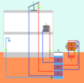
English: Schematic of a heat pump system that uses a rainwater pit as a heat sink. The rainwater can be used at the house for showering (as indicated here), washing hands, flushing the flush toilets (if present), ... Note that the rainwater is herefore connected to the cold water tap of the fossets. This is also why the pipe is connected so low in the rainwater pit.
The heat pump shown here is a ground-source heat pump (ground/water-source heat pump to be exact as it transfers his heat to water which is used in the radiators in the house). [1][2]The heat pump shown has it's heat exchanger dug very shallowly into the soil (1,5m or so). This reduces groundwork, and also makes sense for using it with a rainwater pit (to act as a buffer) as the heat of soil flutuates greatly at this shallow depth in temperate countries, depending on the season. Note that an air-source heat pump (air/water-source heat pump to be exact) can also be used in this setup but is only efficient in countries where it warms up greatly during the day but where it is cool at night, during the entire year. The heat pump would in both cases be fitted with a printed circuit board (PCB) connected to a temperature sensor. The sensor would continuously monitor the temperature of the ground (in the first case) or the air (in the latter case) and if this temperature is high enough, activate the circulation pumps and compressor. If the temperature is too low, it will make sure the circulation pumps and compressor are deactivated. The solar thermal collector indicated is not essential yet helps to warm up the rainwater pit.
References:
|
| Дата | |
| Источник | Собственная работа |
| Автор | Genetics4good |
Лицензирование
- Вы можете свободно:
- делиться произведением – копировать, распространять и передавать данное произведение
- создавать производные – переделывать данное произведение
- При соблюдении следующих условий:
- атрибуция – Вы должны указать авторство, предоставить ссылку на лицензию и указать, внёс ли автор какие-либо изменения. Это можно сделать любым разумным способом, но не создавая впечатление, что лицензиат поддерживает вас или использование вами данного произведения.
- распространение на тех же условиях – Если вы изменяете, преобразуете или создаёте иное произведение на основе данного, то обязаны использовать лицензию исходного произведения или лицензию, совместимую с исходной.
Краткие подписи
Элементы, изображённые на этом файле
изображённый объект
У этого свойства есть некоторое значение без элемента в
29 апреля 2013
История файла
Нажмите на дату/время, чтобы посмотреть файл, который был загружен в тот момент.
| Дата/время | Миниатюра | Размеры | Участник | Примечание | |
|---|---|---|---|---|---|
| текущий | 12:04, 29 апреля 2013 |  | 442 × 436 (6 КБ) | Genetics4good | User created page with UploadWizard |
Использование файла
Нет страниц, использующих этот файл.
Метаданные
Файл содержит дополнительные данные, обычно добавляемые цифровыми камерами или сканерами. Если файл после создания редактировался, то некоторые параметры могут не соответствовать текущему изображению.
| Горизонтальное разрешение | 28,35 точек на сантиметр |
|---|---|
| Вертикальное разрешение | 28,35 точек на сантиметр |
| Дата и время изменения файла | 03:38, 29 апреля 2013 |
